Vibration Welding

Principle of Vibration Welding Machine

Shedule
Connect With Us
today!
You can
contact us on
following numbers
What is Vibration welding?
In Vibration welding, two plastic parts are in frictional contact with each other with certain frequency, amplitude and pressure. As a result of the friction between both parts heat is generated which causes the polymer to melt at the interface. Due to pressure, the molten polymer flows out of the weld zone giving rise to flash. After the vibration has stopped the layer of polymer melt solidifies and a joint I generated.
Equipment’s used in Vibration Welding Process
A vibration welder is basically a vertical machine press, with one moving element, one fixed element and a tooling fixture on both. The vibrator assembly (topside) is a moving element with no bearing surfaces and is driven by either hydraulic pistons or electromagnets. The vibration head and electrical drive deliver the power required to perform the frictional weld process.
The ‘head’ is an electromechanical spring-mass system, which typically has power delivered by electric coils acting upon opposing lamination stacks. With the tooling installed,the mass of the system determines its natural frequency. The drive sends power to the opposing drive coils switched at an electrical frequency tuned to match the natural frequency of the mechanical system, thus, providing constant frequency vibratory motion. The amplitude (a) of the oscillation is a controllable parameter on the machine.
The fixed element is a lifting table (below)which brings the parts to be welded in to contact, by raising the lower tooling and the part to meet those attached to the vibrator head. Guide rails ensure that horizontal positional accuracy is maintained. The lifting table controls the force (F) with which the parts are brought together and controls the penetration depth (s). Both the vibrator head and lifting table are equipped with application-specific tooling fixture .
The tooling must provide good support to ensure that an even pressure is applied to the weld interfaces during the welding. It is essential that there is no relative movement between the parts and tooling fixtures during welding, otherwise the amplitude between the weld interfaces will be reduced. If the amplitude falls below the threshold value, it will result in a poor weld.
The lifting table and hydraulic system are rigidly fixed to a machine frame and the vibration head is attached to the frame by means of isolation mounts, and therefore able to be moved by large forces. The mechanical system is surrounded by a sound enclosure with access doors to the working envelope for operation. A control cabinet houses the drive mechanism, electrical system and PC Control unit.
Vibration Welding Tooling
Tooling is application-specific and will need to be designed uniquely for each program. It is therefore highly recommended that the tooling be planned along with the part design, so that feasibility is covered from the start.
The function of the welding tool is to provide constant, uniform pressure across the weld joint and to ensure that the parts sense the uniform relative amplitude generated by the welding machine. In order to satisfy these requirements, the tooling must be able to rigidly support the entire weld joint, either through direct contact with the welding flange geometry or by transmission of the pressure through structural portions of the shell geometry itself.
Well-designed tooling consists of an upper tool that is mounted to the vibration head and a lower tool that is mounted to the lifting table. The parts are placed into the fixturing details of the tool at the start of each cycle.
Tooling construction typically consists of hardened steel segments that are CNC cut to the part shape. These details may be on moving tool actions in the lower tool only. The upper tool cannot have any tool actions,as the forces imposed during the process would cause the tool to fail. It is important to understand these points for part design so that access to the weld joint on the part upper shell can be planned without tool actions.
An improper tool design that does not provide constant, uniform pressure across the weld joint or allows the parts to slip relative to each other, thereby not providing the uniform relative amplitude, will result in a loss of process control and the production of nonconforming parts.
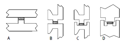
Joint designs : Butt(A). Butt with U-Flange (B), Tongue and groove with U-Flange (C). Double tongue and groov (D)
Advantages of Vibration Welding
- Relatively Short Cycle time
- Energy Efficient
- No additional materials are required to place between the workpieces.
- Capability of welding large parts
- Multiple cavities tooling is possible for smaller parts
- Produce high strength, pressure-tight hermetic seals
Applications
- It is widely used in Automotive industry: Instrument Panel to PAB chute welding Instrument Panel to Defrost Duct Welding Glove Box Engine Cam Cover Engine Air Duct Oil Mist Filter Lamps
- Appliances Washing Machine Drum Welding Dishwasher Pump
Call On +91 9137903310 OR ![]()